Saturday 21 November 2020

Rub Rails | First Laminate Test Fit

When cured I moved the first laminates into the workshop for cleaning up and test fitting.

Here you can see they were so long that they only just fitted inside. I am using the saw horses for support while cleaning up the second glued scarf joint on the starboard laminate.


Fitting this first laminate requires temporary screws driven into the hull to pull it into place. I didn't like the sound of this, but I couldn't see any alternative.

So, I went along the side of the boat and used bits of tape to mark where screws would need to be driven.

I didn't mind doing this in the sealed buoyancy compartments in the seatbacks, but refused to make holes inside the beautifully finished seatback locker interiors. Some sort of clamping would be required on this part of the rails.

I hoped that just three screws would suffice in the cabin - the holes would be easily filled when painting the interior.

And at the stem we have the substantial lower breasthook, made of 18mm ply and ideal for using some long screws to pull the end of the rail into place. I decided to use three screws here.

That didn't seem too bad, so I then offered up the starboard laminate and similarly marked up where holes would be required for the screws.

Holes for 4 x 50mm screws were drilled accordingly, and the bevel required on the bottom of the rail was planed.

The laminate was then carefully fitted, starting in the middle where the bend is slight and working outwards to the stern and the bow.

It worked out really well.

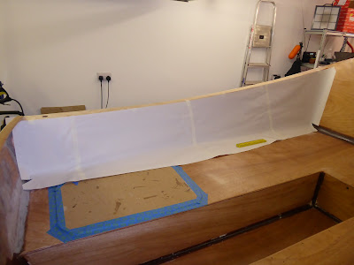
Here is how I pulled the laminate into place over the seatback lockers at the stern, using a pair of large F clamps.


These clamps were a gift from my son a couple of years ago, and they are really useful. Thanks Nick!

This is how the laminate curved from the cabin all the way to the bow. It's a lovely fair curve but what you can't see here is the small gap between the rail and the hull. This would need to be fixed, somehow.


The laminate bent well and didn't fight back too much - even at the bow. I was fairly pleased with this outcome so retired for the day.

The following morning I inspected the gap and thought about drilling more holes in the hull, and remembered that I had fitted a substantial sheerclamp to support the forward deck.

I did this because the manual calls for an epoxy fillet here, which seemed ridiculous to me.

So ... no problem here and more temporary screws could be deployed to close the gap.

I marked where the screws would be required, removed the laminate and drilled more holes, and then refitted it.

This is what it looked like.


Looks good and gap closed!

Here is the view along the rail from the stern of the boat.


There is a lovely fair curve all the way to the bow. I was delighted!

Next I cleaned up the port laminate scarf joint on the sawhorses, as here.


I marked up and drilled the port laminate exactly the same as its starboard counterpart, and fitted it in the same way.

Here is a view of the  laminate at the bow and topside.


And here is the view looking astern.


That was very successful, and a lot of fun!

Upper Hull | Sanding & Patches

While waiting for the rub rail laminates to cure I sanded the fibreglass which now covered the upper hull.

As expected, this was a fairly tedious experience but made bearable by having decent sanders to work with.

There is not a great deal to say about sanding, but here are some pics anyway.

This is the starboard cockpit deck and seatback, freshly sanded.


 And this is the starboard topside and cabin top, seen from the bow.


Same side but seen from the stern.


I snipped the support piece out of the rear cabin wall before sanding here, to add some excitement to the process.


This is the cockpit and rear cabin wall, sanded and seen from behind the boat.


Inevitably, I managed to sand through the layer of fibreglass in a few places.

I marked them with a bit of blue tape as it happened, so that I could easily find them to patch them later.

As here on the front cabin wall and Dorade boxes.


Finally, when all the sanding was complete I made fibreglass patches and wetted them all out.

I will sand and feather-edge them at some point when the sanders are in action again. This is the cockpit, with its patches in place.


Not too pretty, but cleaning up will have to wait while I make the rub rails!

Rub Rails | Gluing Scarf Joints

As mentioned in the previous post, each rub rail is built up from three laminates, and each laminate consists of three lengths of Sapele - two long and one short.

Now, the build manual suggests that the laminates are made by gluing the three separate pieces directly to the hull, rather than making a single full length laminate which is then fitted to the boat in one piece.

I didn't like the sound of that. It is vital that the rub rails have a perfectly fair curve, and that would be most easily achieved by fitting a single full length which would naturally form its own pure curve.

I also thought that a single long piece would be easier to bend than three shorter ones.

So I decided to make the laminates first.

I began by gluing one short and one long piece together for all six laminates.

First I made a test fit in the workshop. Here is what it looked like.


Each scarf was clamped with three spring clamps, which did the job nicely.

You can also just see that I clamped each length of Sapele in place with G clamps i.e. the short as well as the long pieces. As I did this I realised that some of the pieces were not perfectly true, and had a very slight twist to them. Clamping these pieces down was pulling the scarf joints out of true, so that was not a good idea.

Always best to do a test fit, even when it doesn't seem totally necessary ...

I also said in the previous post that I labelled each piece, to avoid any confusion when gluing up the laminates. This proved very useful. Here is such a label.


When satisfied that the scarfs were tight and true I glued them together, as here.


Just one length is clamped down for each joint, allowing the spring clamps to pull the scarf together.

That went well. The joints looked good when glued up. Like this.


While doing all this it became very obvious that there was not enough room in the workshop to glue up the third piece, to make the full length laminate. So that would have to take place inside the house.

Once again a test fit was carried out. It turned out that there was only one place where the laminates could be made and then successfully removed from the house, and that required the use of two rooms. This is how the test fit looked.


This time I found that it helped to clamp the straightest pieces on both sides of the scarf, to steady the now very long lengths of wood and stop them wobbling.

Again, when happy that everything fitted properly I glued the joints - taking great care not to drip epoxy on carpets and furnishings in the process. Here is what it looked like.


Here is a closer view of the joints themselves.


I left the laminates to cure for several days, to be sure that they would be strong enough to move back into the workshop for fitting.

We're getting there!

Sunday 8 November 2020

Rub Rails | Cutting Scarf Joints

The day finally came when my next activity was making and fitting the rub rails which run along the sides of the boat.

Like the toe rails, I started this while covering the upper hull with fibreglass, and waiting for resin to cure.

I broke out the lengths of Sapele hardwood supplied for the rails.

Each rail is made from three laminates, fastened one at a time to the full length of the hull. And each laminate consists of three pieces of Sapele, scarfed together to make a single length.

That's a lot of wood, and a lot of work!

Scarf joints are made on a 10 to 1 basis for the length of the scarf and the thickness of the wood respectively. I hope that makes sense.

Our Sapele is 20mm thick, so each scarf will be 20cm long. Simple.

It is essential that that the scarfs are accurately made, so it takes a lot of time to mark them up and cut them out.

Here I am marking out the length of the scarf, using a metric steel rule and an engineer's square to make sure that the joint is exactly 20cm long and square.

Next the joints are marked out using a steel rule and a marking knife, like this.


The steel rule is held firmly in place with a couple of spring clamps, which allow it to be positioned very accurately. You can't hold it in place by hand - it doesn't work.

Then the joint is firmly but carefully marked up with the knife. I have got a fancy Japanese marking knife but I found in practice that a craft knife with a new blade was easier to use and very effective.

The rule needs to be as heavy and stiff as possible, which is why I like the rule in the above pic. I stole it from the metalwork shop when I was at school - it's so old it predates the metrification of the UK, and is only marked in inches. I love it!

It's important to use a knife rather than a pencil, for the reasons given in the previous post. A pencil line is not visible on the dark wood. The knife cuts a deep line which is easy to see and shows as a bright stripe when the plane blade reaches it. 

I devised a method for labelling each piece so I would know which laminate it belongs to, and which of the three constituent pieces it is. 


All the scarfs must slope in the same direction, fore and aft, for looks. And the pieces must be numbered and labelled Port and Starboard, pointing forwards.

This will avoid much confusion later, with 18 pieces of wood to handle.

The pieces were bundled together to await the cutting of joints, with one bundle for each laminate.


I planed the first four joints before deciding that there must be a faster way of doing this.

So I fitted a rip cut blade to the Japanese saw and used it to remove nearly all the waste, like this.


 This is very quick and achieves a clean and accurate cut. As seen in this pic.


The scarf is then clamped in the vice and planed down to the line with a jack plane, as here.


Finally, the scarf is moved to the other end of the bench and clamped in place to be finished with the block plane. Like this.


This results in accurate, close fitting scarf joints.

Here are the scarfs all cut and ready for gluing, stored in bundles for each laminate.


That was a lot of fun!


Toe Rails | Making & Test Fit

I made the toe rails that run along the edge of the cabin roof while I was covering the upper hull in fibreglass cloth. It was a welcome distraction and a good use of time while resin was curing.

The toe rails are made from Sapele hardwood, which will look nice when oiled or varnished. The stock supplied in the timber package was oversize so had to be reduced to the specified 3/4" square section.

I did this in the vice with a jigsaw, as here.


Then it was planed to a straight edge with the jack plane, and finished with the block plane. Like this.


Next I drew a diagram of the required trapezoidal section for guidance, as in this pic.


Then I marked up the rails accordingly, using my trusty old cutting gauge as illustrated here.


The cutting gauge is fitted with a small sharp blade rather than a pin, and is used to mark up long lengths of timber for ripping. Here it is in close up.


The blade cuts a fine line along the grain, as deep as you wish to make it. This is much more visible than a pencil line on the dark wood, and it is very easy to know when you have reached the line because it shows as a bright stripe along the edge of the workpiece when you hit it with the plane blade. That's enough about the cutting gauge ...

It was clear from the diagram that the rails would be difficult to shape. As usual the manual tells us to use the tilting table saw which we do not possess, so the rails would have to be planed to shape.

There was no way to hold the rails down on the bench or in the vice to allow them to be planed, so I fastened them to a length of scrap.

By clamping the ends of the scrap piece to the bench it was possible to hold the rails rigid and plane them to the required section, as in this pic.


It took a lot longer to do than just running the rails through a table or band saw, but it worked out just fine.

This is the resulting trapezoidal profile.


Next was to decide how best to bend the rails into place for a test fit. Now that they were reduced in mass by sizing and shaping they felt quite pliable.

I marked out the curve of the cabin roof edge on a board and made a test bend of a rail, clamping it in place. This is it.


That was quite easily achieved, so I then drilled holes in the rails for temporary screws to fasten them to the cabin roof. As here.


The manual shows that the builder used seven temporary screws in his rails, but I felt that the curve at the forward end was a bit too stiff and needed another screw in the Dorade box area.

Here is the starboard toe rail test fitted to the roof.


And here is the front end of the rail, showing the three screws holding it in place on top of the Dorade box.


I wondered about where exactly to site the rails, in relation to the edge of the roof.

In the end I installed them right on the edge because this allows the temporary screws to be driven into the sheerclamp as well as the deck, providing good holding.

The manual states that the rails will be 48" long when fitted and finished, so I will have to trim an inch or two off the front end when installing them. That can wait.

The rails were finally set aside to await installation when the cabin roof has received its requisite three coats of epoxy resin.

Saturday 7 November 2020

Fibreglass | Transom Inboard Panel

When I 'glassed the footwell I omitted to add an overlap from the rear face of the footwell up onto the transom, to accept the final panel on the inside face of the boat's stern. By the time I realised this it was too late ... the footwell was all 'glassed out!

So before adding 'glass inside the transom I had to make an overlap with a scrap of cloth.

Here is the overlapping patch, wetted out.


When cured I sanded and feather edged the patch.

I had previously made a pattern for the inside face of the transom and transom skirt, and used it to cut out  a 'glass panel.

Finally I carefully wetted out the panel with a disposable roller, working down from the top edge and from the middle outwards so that the cloth would not sag or drop.

Here is the finished article.


Looking nice, and hopefully no more fibreglass work until the boat is turned upside down to finish the lower hull!


Fibreglass | Seatbacks & Cockpit Deck

As usual the first task when making 'glass panels for the seatbacks was to make a pattern.

Here is the paper pattern, test fitted inside the port seatback.


You can see that the pattern continues out across the cockpit deck, covering the outboard edge of the deck and overlapping onto the single full width sheet of cloth laid fore and aft along the centreline of the deck.

In this way we cover both seatbacks and the whole deck with just three 'glass panels. Neat, huh?!

Lastly the cloth panels were cut, fitted and installed.

There isn't a whole lot to look at but here is a view from astern of the wetted out seatbacks and deck.


Nearly done with fibreglass for the time being - just the inside of the transom to go!

Fibreglass | Topsides & Seatback Tops

The build manual suggests that it might be easier to 'glass the front and rear topside panels (fore and aft of the cabin topside area) when the boat is upside down.

I can't see how that would be a good idea, when it is an easy task to cover the entire upper hull with 'glass cloth all in one go.

So that's what I did.

First the overlaps from the cabin roof and topside panels were sanded and feather edged to accept the additional topside panels.

Here is the starboard overlap onto the rear panel, nice and smooth.


And here is the starboard overlap onto the forward panel. Again, nice and smooth.


Patterns for the topsides were made by laying paper along the panels and scribing in the curves and overlaps.

This is the rear topside pattern taped in place for a test fit on the port side.


And this is the pattern for the forward topside panel, taped in place on the starboard bow.


Next the patterns were taken inside the house to cut the 'glass panels. There isn't any room in the workshop to do this.

Here the patterns are held firmly in place on the rolled out cloth by a couple of stuffed chicken door stops. They work well, and don't talk back.


While marking out the cloth for each rear topside panel I added an overlap of 15cm to the top edge, so that the same piece of cloth will cover the seatback top and overlap down the seatback into the cockpit.

Here I am marking in the overlap on the 'glass cloth.


 I just use a rule to mark the cloth 15cm away from the edge of the paper pattern.

Then as always the cloth is cut just inside the marks to get a correctly fitting 'glass panel.

Here is the rear topside 'glass panel fitted and held in place on the starboard side, ready for wetting out.


And here is the forward topside 'glass panel clipped in place on the starboard bow.


Clear resin was then applied with a disposable roller to wet out all the panels.

This is the forward panel on the port side.


And this is the rear panel, again on the port side viewed from the front.


In the following pic you can see where the topside 'glass panel extends across the seatback top and overlaps down onto the seatback itself, in one seamless layer.


I carried the inside overlap down to the top edge of the seatback locker openings.

And finally here are the the newly covered topsides, seen from port at the stern.


Looking good!