Saturday, 15 July 2023

Fitting Out | Mainsheet Block Issues

As mentioned in the previous post, I was able to fit all of the deck hardware apart from the mainsheet ratchet block. There was a significant issue with it.

It is supplied with machine screws and dome nuts for through deck fastening, even though this is not possible. The mainsheet block is located on the cockpit deck in the centre of the forward wall of the footwell, right on top of the centreboard case. It is impossible to install it there.

I read on the PocketShip forum that one builder had addressed this by drilling screw holes into the centreboard case and using the inspection port to somehow tighten the nuts from the inside. That seemed highly unsatisfactory. What I would call a 'bodge'.

I am guessing that every builder who purchases the hull hardware kit hits this problem, which again makes me question why such issues persist after so many years of production. It should not be this way!

I decided to make a pad to allow the block to be installed in the right place but properly supported and using through deck fastenings.

I made a drawing of the support pad, as here.


This will allow the block to be through fastened to the pad with the nuts being contained in a recess underneath the pad. The wider pad can then be through fastened to the deck, either side of the centreboard case.

This piece of cardboard shows where the pad will sit.


I made a second drawing to make sure that the pad fastenings would be located well outside the sides of the case and its cleats. This is it.


I made the pad from two thicknesses of 9mm ply, with a recess cut in the bottom layer. Here it is being glued up.


Then the pad was cut to size and planed fair, like this,


Holes for the fastenings were drilled in the pad, as here.


This view from underneath the pad shows how the block will be fastened through the top of the pad, with its locknuts in the circular recess.


 And this is how the mainsheet ratchet block will look when installed on the pad.


Then I gave the top of the pad a 3/8" round over on the router table, to make it elegant as well as functional. Here it is in progress.


A couple of clear coats of resin were applied and sanded smooth before the first coat of primer. This is it.


The small squares are part of an experiment to solve the ventilator fitting conundrum. I will explain later ...

More primer and lots of gloss will follow before polishing and fitting with the block. A lot of work to resolve a simple design issue!


Fitting Out | Deck Hardware

While I was struggling with the ventilators, I started to fit the deck hardware.

Some of the machine screws provided are too long because they are fastened with dome nuts and have to be exactly the right length.

This means careful measurement and cutting and filing, like this.


I also needed to purchase quite a lot of new fastenings because of the way I had installed the boom gallows tubes and stern mooring cleats.

And then came the challenge of drilling exactly perpendicular holes through the blocking inside the seatback tops. This is extremely difficult to do freehand, so I used my drill guide.

Here it is being used to drill holes for the boom gallows stanchion supports.


This was fine for the two holes in the front of the fitting, but there was no room to use the drill guide for the two rearmost holes. So, I inserted a length of threaded rod in one of the holes I had already drilled to act as sighting guide when drilling by eye. Like this.


The resulting holes were not perfect but were good enough for a secure fit.

I had a lot of trouble with the stanchion support on the port side of the boat. The support tube did not fit into it and I assumed that it was the wrong size at 7/8" instead of 1".

The kit supplier sent me a replacement which fitted the tube but had an uneven bottom which caused it rock on the seatback top. So that was no good.

So, another replacement was sent and that cured the problem.

I now had two unusable stanchion supports sitting on my shelf and when I compared them I quickly saw that the first one was in fact the right size but had not been machined correctly.

You really do have to wonder about the manufacturer's quality control, or lack thereof.

Final installation of various bits of hardware followed, entailing bedding them in marine sealant.

This is what I am using.


It is Geocel Marine, formerly known as Dow Corning and highly recommended.

We use silicone rubber sealant on fixtures and fittings which do not require permanent installation.

I bought this tube three years ago when fitting inspection ports in the centreboard case and bulkhead 1 and I wondered if it was past its use-by date. The vendor didn't seem to know so I cut the nozzle and tried some out. It looked fine and set nicely so I am using it for the rest of the hardware.

Methylated spirit and kitchen roll clean up any squeeze out easily.


Here is one of the stern mooring cleats, sealed in place.


And here is the starboard stanchion support with boom gallows tube fitted.


Here is the port fitting.


Sockets are needed to get to the nuts inside the seatback locker, and a screwdriver to hold the screw while it is being tightened.


I found that a syringe was quite useful for accurate application, like this.


The drawback is that the sealant hardens in the syringe nozzle so it cannot be reused.

I eventually did the final fit of the hardware in the forward deck well and cabin roof.

Here are the starboard halyard cleats.


And here are the starboard jib sheet cleat and halyard cheek blocks.


This is the hardware on the forward deck and tabernacle. You can see the forward mooring cleats, the jib halyard cleat, and the starboard halyard lead blocks.


The only piece of deck hardware which I could not fit was the mainsheet ratchet block, which will be the subject of the next post.


Ventilators | Cutting New Holes

I explained in a previous post how I cut the holes for the ventilator cowls in the wrong place and had to do a lot of work to fill them and refinish the tops of the Dorade boxes.

This really annoyed me, but these things happen and we have to press on regardless. Which entailed cutting new holes in the cabin roof. Not something I was looking forward to ...

First I used masking tape to outline the cleats inside the Dorade boxes; where the halyard cheek blocks would be located; and lastly where the new holes should be cut.

Here I am making the first hole with the Japanese keyhole saw.


It's much easier to drill holes and cut the hole like this than using a jigsaw.

The roughly cut holes were then shaped with a rasp and an abrasive cylinder in the drill. Here they are.


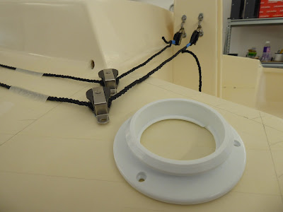
A test fit of the ventilator followed, like this.


It became apparent that there was a problem here.

The inner piece screws into the outer flange from inside the Dorade box to close the ventilator, and I had assumed that it would bear directly onto the roof to make a seal.

However, the outer flange is secured with machine screws and locknuts which protrude into the Dorade box and prevent the inner piece from closing. It simply grinds against the locknuts.

I will have to give this some thought to find a way around the problem.

On the face of it seems that the ventilator is badly designed. To allow it to be closed fully there cannot be any fastenings inside the box, which would mean using very short wood screws which would not be strong enough.

I contemplated making a gasket to go inside the box which would allow the locknuts to be recessed, out of the way. I even started to make it, as here.


I soon realised that the gasket would not allow the inner piece to be screwed up because its thread is too short!

So I can't see how this can work at all.

More thought required.

Tuesday, 13 June 2023

Rudder | Test Fit

I left the rudder pivot eyes to cure for a while and then had a quick test fit of the rudder and tiller.

Here it is seen from starboard.


I was a bit dismayed to find that the slot for the tiller is slightly too low in the transom, as you can see here.


And here.


It works just fine but it looks like some cosmetic surgery will be required at some point.

I also think it could be a little wider to accommodate tiller movement.

I doubt very much that this will be the only modification!


Rudder | Installing Pivot Eyes (2)

I sat the rudder against the transom, at its correct height, and marked up the location of the two pivot eyes.

Here I am drilling the hole for the lower eye. I used a pencil line to guide drilling at the correct angle, as I did on the keel.


As with the keel eye I again used 3M 5200 adhesive sealant to secure and seal the eyes. This is the lower eye.


And this is the upper eye.


Very smart!


Hull Hardware | Marking Up

The time came to begin installation of the hull hardware.

Still smarting from the consequences of cutting the ventilator holes in the wrong place, I was resolute that I would plan this process very carefully and mark the exact location of everything before drilling any holes.

Working from the rear to the front of the boat, this is what I did.

At the stern the stanchion supports for the gallows boom poles are already loosely in place. I marked the location of the rear mooring cleats in front of the poles, and the hole for the mainsheet bridle in front of that. Like this.


I won't drill the hole for the bridle until the boat is rigged and I can see where it should ideally be.

The location of the hardware on the cabin roof and tabernacle had to be exact so I fixed the components in place with Blu Tack until I got it just right.

Here are the halyard cleats at the rear of the cabin roof.


And here are the halyard cheek and lead blocks at the front of the roof and on the tabernacle.


I used a piece of old line to make sure everything lined up properly and located the ventilator in place at the same time.

The position of the jib sheet cam cleat is measured from the stem, so I made a measuring stick for this purpose. Here it is in use.


And here is the marked-up location for the starboard cam cleat.


Then I marked up the tabernacle, like this.


Then came the cabin roof, as here.


And at the rear of the roof the halyard cleats were marked up.


It will not be possible to know the exact position of the spinnaker sheet cam cleat until the boat is rigged, but I did know from conversations with other builders that that it would be between two points, so I marked them in. Like this.


The location of the mainsheet ratchet block and the centreboard pendant cleat were easy to determine. Here they are.


Fastening them in place will be a different matter. They come with machine screws and nuts for through hull installation, but they are both seated on the centreboard case so will require screws. I am wondering if that will be sufficiently strong for the ratchet block.

The location of the chainplates cannot be determined until the mast is up and the shrouds rigged, but it is again made by measuring from the stem. Here is the measuring stick.


The chain plates will be somewhere on this line, raked slightly backwards.


That's it for now. It will soon be time to drill holes ...


Cabin Interior | Refresh

The interior of the cabin and the storage compartment had become a bit tatty and discoloured over the course of the build and I decided some time ago that I would repaint it at an appropriate moment.

The moment seemed to arrive when I started to plan hardware installation, so I purchased fresh paint and cleaned up inside the boat.

I masked off the portholes to prevent paint running down the topsides. Like this.


The paint I am using inside the boat is top quality, oil-based household paint. It is suitable for exterior use and I think it's a better choice than marine paint for the interior.

It is an eggshell finish (semi matt) so easy on the eye, and it's brilliant white so it contrasts nicely with the ivory white of the topsides.

Two coats were applied with a short-felt roller. This is the finished cabin looking aft.


And here it is looking forward.


That's better!